According to research conducted by Boeing, almost 50% of all aviation accidents, and incidents occur during the final approach or landing. You must be wondering if there are technologies to mitigate such events.
Well, there are Non-precision Approach (NPA), and Precision Approach (PA) systems that are important for a safe landing. We have already discussed NPAs like RNAV Approach, and RNP Approach in our previous technical blog.
So, what about the Precision Approach Systems?
An Instrument Landing System (ILS) is one of the widely used Precision Approach systems that offer an accurate approach, and landing guidance.
Today, we are going to explore ‘What is an ILS Approach?’ with its types, working procedures, technical terminologies, flying guides, and more.
Table of Contents
What is an ILS Approach in aviation?
ILS stands for Instrument Landing System, and it is a precision runway approach system assisted by two radio beams. In contrast to the Non-Precision approach like RNAV, ILS is the most precise, and accurate approach when pilots are in IMC (Instrument Meteorological Conditions) approach.
The ILS approach is supported by two radio beams offering lateral, and vertical guidance for precision approach procedures. Talking about efficiency, ILS can handle up to 29 arrivals per hour on a single runway without any safety issues.
On one hand, ILS enhances safe flight operation, and on the other, it offers greater flexibility in scheduling passenger and cargo service. There are various categories of the ILS Approach which we will discuss below.
Before knowing how an ILS approach works, let’s familiarize ourselves with the key terminologies and components of the ILS System.
Guidance Information, Range Information, and Visual Information are the three important components of the ILS system.
- Guidance Information – Localizer (LOC) and Glideslope (GS)
- Range Information – Distance Measuring Equipment (DME) and Marker Beacons
- Visual Information – Approach Lights, PAPI Lights, Centerline Lights, Runway Lights, and Touchdown Lights
What are the 2 radio beams used for an ILS approach?
ILS Approach uses two radio beams to assist pilots with vertical, and lateral guidance during the landing approach. Glideslope (GS), and Localizer (LOC) are the two beams that offer vertical, and horizontal guidance respectively.
Localizer (LOC)
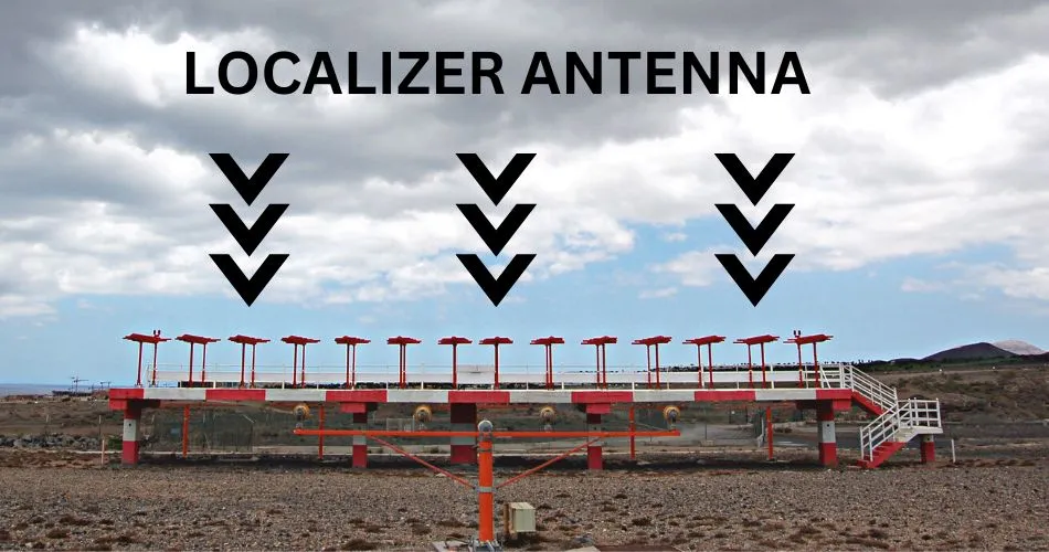
You can find the localizer antenna usually at the end of the runway, and it is responsible to provide lateral, or horizontal guidance for the runway centerline alignment.
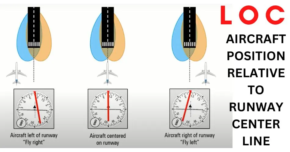
Two intersecting beams are projected by the LOC; one slightly to the right of the centerline, and the other slightly to the left. As these two beams intersect, the ‘on LOC’ is achieved meaning the aircraft is on the correct centerline path.
The LOC status is displayed on the Primary Flight Display (PFD) which shows the aircraft’s displacement from the runway centerline.
Glideslope (GS)
Glideslope is one of the two crucial components of the ILS Approach that provides vertical guidance to keep the aircraft in a proper descent path while landing safely on the active runway.
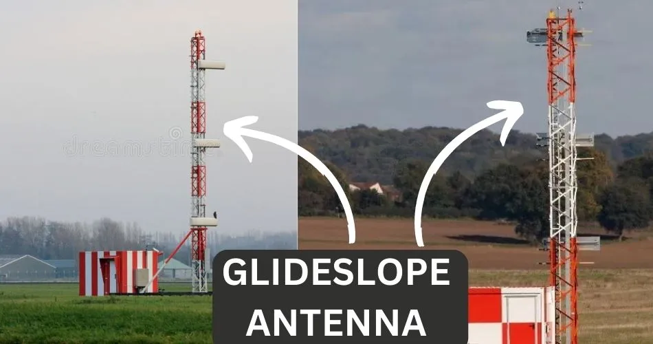
Normally located on the aerodrome, GS is responsible to guide the aircraft from the Final Approach Fix (FAF) to the Decision Altitude (DA). Like Localizer, Glideslope also transmits two narrow intersecting beams, and the signals are emitted in the direction of the LOC front course.
The 2 intersecting beams (one below the required vertical profile, and the other slightly above it) allow Primary Flight Display (PFD) to indicate the aircraft’s position above or below the GS. By observing the PFD, pilots can confirm whether the aircraft is on the proper glide path, or not.
Glideslope Projection is normally adjusted for a 3-degree glide path however, there might be certain exceptions due to terrain, or noise abatement.
Marker Beacons
Marker Beacons are also an important component of the ILS Approach however, they are not mandatory. If available, these beacons provide a range of data along the approach course.
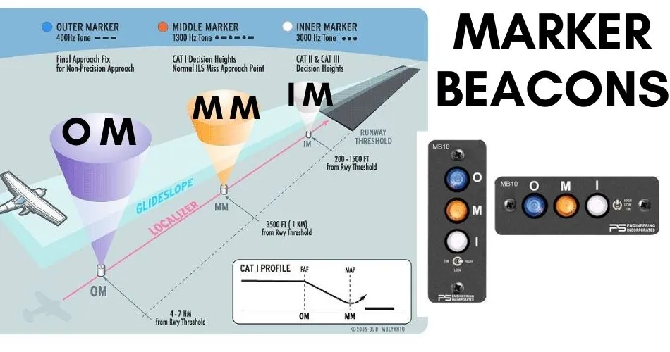
Outer Marker (OM), Middle Marker (MM), and Inner Marker (IM) are the three marker beacons associated with an ILS Approach. Some ILS approach may not offer Inner markers. Besides, there may be a Back Course (BC) Marker during the back course LOC Approach.
These Marker Beacons are used to verify the aircraft is on the correct path for an ILS Approach. The OM beacon is normally located 5 nautical miles from the touch-down whereas the MM beacon activates 1 nautical mile from the touch-down. IM beacon is rarely used because it is seen near the final touch-down.
An aircraft conducting an ILS approach must pass through the Marker Beacons for an accurate ILS landing.
Distance Measuring Equipment (DME)
DME Equipment is a type of navigation technology that measures the slant range/distance between an aircraft and a ground station.
DME can be automatically used with the ILS or it can be used as separate navigational aid offered by other systems such as VOR.
Morse Code
ILS Frequency ranges from 108 MHz to 112 MHz, and Localizer transmits the ILS facility identification code. Due to the small frequency range of ILS, you might pick up the wrong ILS Frequency at a nearby airport.
To prevent this situation, ILS emits its own Morse Code which is unique for every airport. For example, the identification code for Los Angeles International Airport (LAX) is I-MKZ.
This Morse Code is generally displayed in the ILS receiver instrument. If not, you have to listen to the Morse Code, and compare it to the one on your ILS approach chart. The ‘Beep’ sound is activated to verify the Identification code.
Tuning the ILS frequency, and listening to the Morse Code are almost faded out due to the advancement of technologies. However, some aircraft still need this procedure.
Approach Lighting System (ALS)
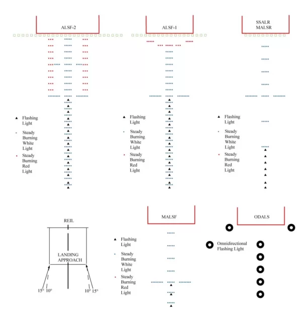
Lighting Systems at the approach end of a runway is referred to as the Approach Lighting System (ALS). This system consists of a series of lightbars and strobe lights that offer visual guidance for the final approach.
ALS enhances visibility and also assists pilots in conducting ILS landings during reduced visibility. The image below shows the types of Approach Lighting Systems.
What are the categories of ILS?
There are three general categories of ILS approaches in current practice which are CAT I, CAT II, and CAT III (autoland). Let’s explore each category in detail.
CAT I Approach
CAT I is known as the basic ILC approach as it features fewer requirements. Instrument-rated pilots can conduct CAT I ILS Approach with properly equipped aircraft.
The Decision Height (DH) limitation for CAT I ILS Approach is not less than 200 ft. Likewise, the runway visibility requirement is greater than or equal to 1800 ft. Once the aircraft reaches this DH or Height above touch-down, pilots need to disconnect the autopilot, and manually land the aircraft.
CAT II Approach
CAT II ILS Approach features lower minimums than CAT I ILS. The required height above touch-down or the decision height for CAT II is not less than 100 ft. Talking about visibility, CAT II requires at least 1,200 ft of visibility.
There are some strict requirements to conduct the CAT II approach including pilot certification, operator’s certification, aircraft compatibility, and standards of the ILS equipment.
CAT III Approach
CAT III ILS Approach is the most complex, and high-cost ILS system that requires special certification for operations, flight crews, aircraft, and airborne/ground equipment.
CAT III ILS is able to facilitate autoland that’s why it requires authorized pilots to make approaches in adverse weather conditions.
The Decision Height and Runway Visual Range of the CAT III ILS Approach depend on the sub-categories including CAT III A, CAT III B, and CAT III C.
Decision Height is not applicable to CAT III ILS landing. Talking about the Runway Visual Range (RVR), CAT III A requires at least 700 ft, and CAT III B requires at least 150 ft whereas there is no RVR minimum requirement for CAT III C.
CAT III C is also able to execute autoland.
| ILS CATEGORY | DECISION HEIGHT/HEIGHT ABOVE TOUCH-DOWN | RUNWAY VISUAL RANGE (RVR) |
| CAT I | Not less than 200 ft. | Not less than 1,800 ft. |
| CAT II | Not less than 100 ft. | Not less than 1,200 ft. |
| CAT III A | No DH | Not less than 700 ft. |
| CAT III B | No DH | Not less than 150 ft. |
| CAT III C | No DH | No RVR Minimum |
We explored all the basic components and terminologies related to an ILS Approach System. Now, let’s find out the working mechanism of this precision approach.
How does an ILS Approach work?
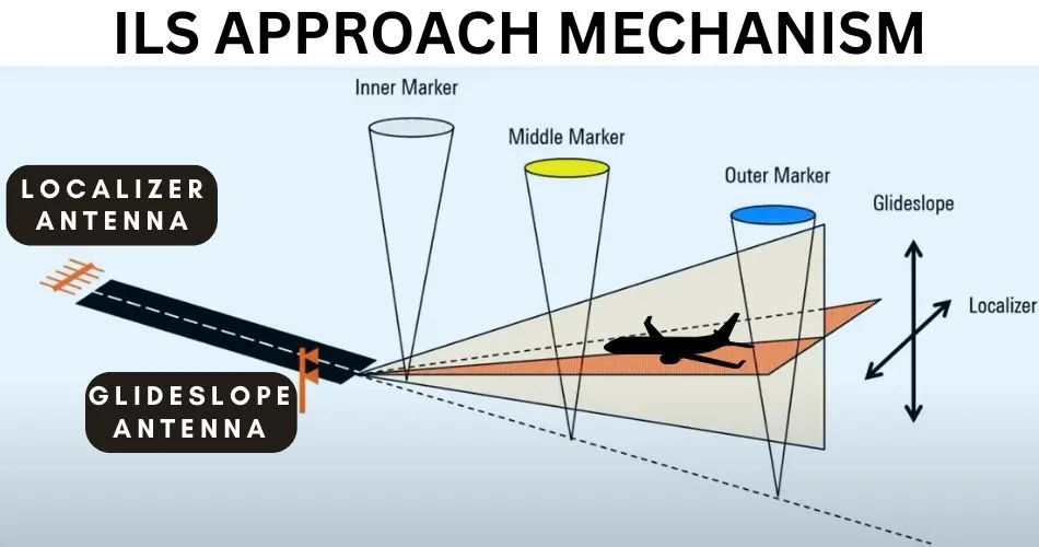
For an ILS approach to work, the airport must be equipped with necessary ILS equipment like Glideslope (GS), Localizer (LOC), ALS, and so on. The airport must also be approved by the aviation regulations for ILS Approach.
Other requirements include operator certification, aircraft compatibility, and flight crew training.
Before commencing the ILS approach, the necessary ILS Approach chart is required which must include the crucial information listed below.
- ILS Frequency and Identifier Code
- ILS Inbound Course and Glideslope Angle
- Final Approach Point
- Minimum Descent Altitude/Height
- ILS Categories
- Go-Around/Missed-Approach Procedure
To visually understand ILS Approach System, you can watch the following video created by popular pilot Captain Joe.
How to fly an ILS Approach?
The pilot flying the aircraft must use the ILS frequency to let the Glideslope, and Localizer capture the aircraft. Once the ILS frequency is activated, the LOC, and GS equipment will begin to guide the aircraft toward the runway.
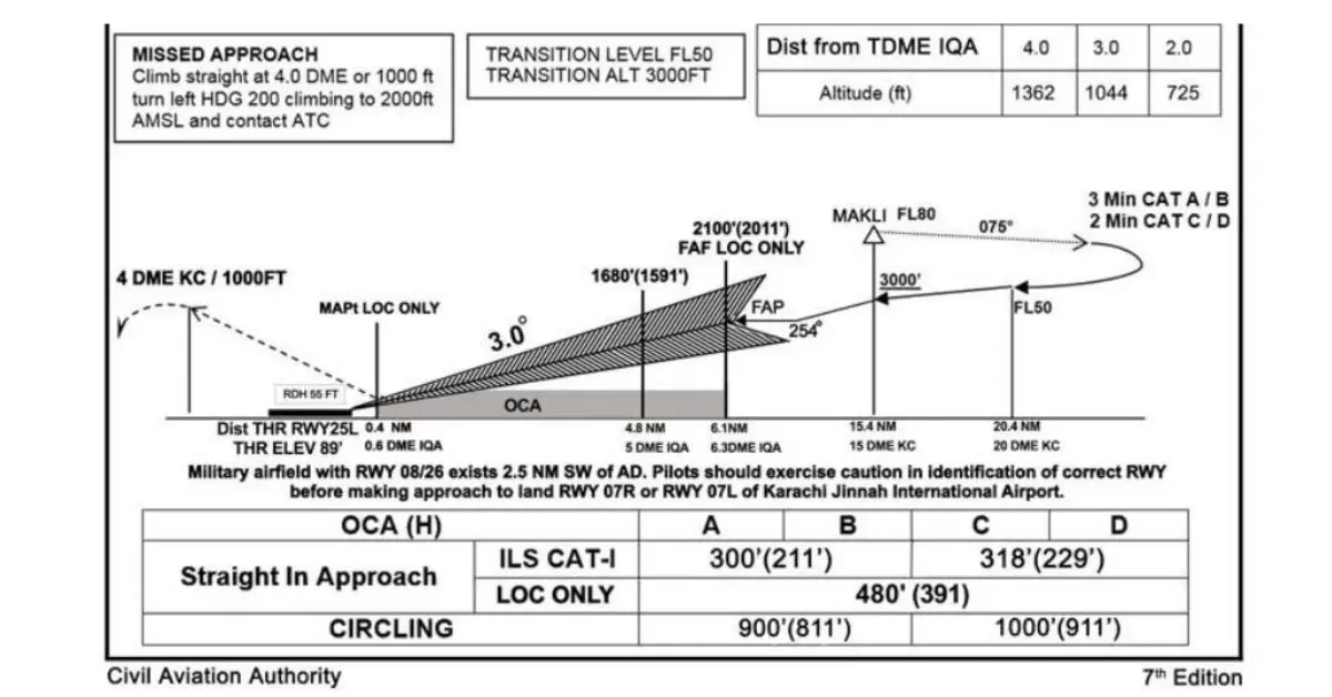
The ILS Approach begins from the Final Approach Point or Final Approach Fix as shown in the chart above. You must activate the ILS frequency so that, the LOC, and GS captures your aircraft when you reach the final approach point.
Localizer will maintain the runway centerline while the Glideslope handles the descent of your aircraft.
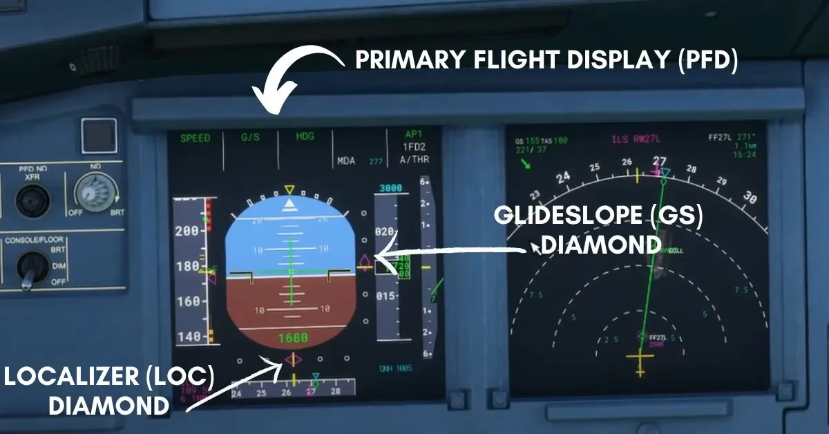
The LOC position is shown by the Diamond indicator (shown in the image above) in the PFD which indicates the aircraft’s position relative to the runway centerline.
If the Diamond is to the right, the aircraft is to the left of the landing runway, and vice versa.
GS position is also represented by the Diamond indicator in the PFD, and it shows the aircraft’s displacement relative to the Glideslope.
If the Diamond is above the center, the aircraft is below the GS which will require the pilot to reduce a vertical speed or even level off to recapture the glide slope.
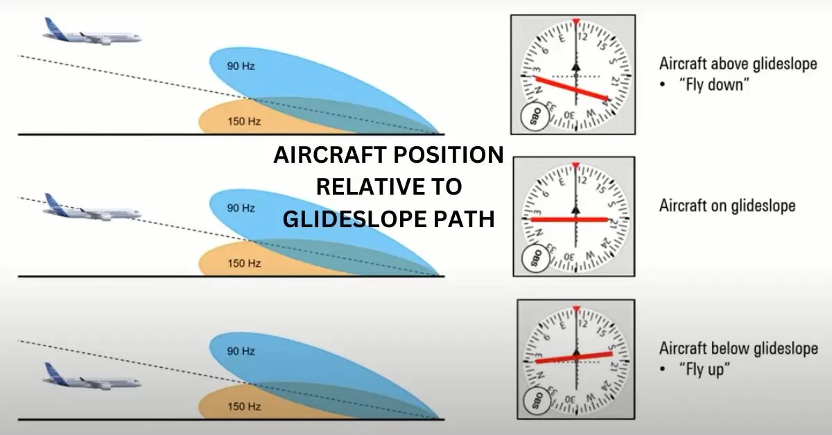
Likewise, the Diamond below the center means the aircraft is above the GS, and the pilot must correct vertical speed to rejoin the Glideslope.
Depending on the ILS category, you need to be aware of the Decision Height (DH). In the chart above, the ILS Category is CAT I so, your DH must not be less than 200 ft.
As the ILS system guides your aircraft to the DH, you need to disengage the Autopilot, and manually land.
Watch this video by Captain Joe where he demonstrates flying an ILS approach with the Airbus A320.
Do all airports have an ILS system?
All airports don’t feature an ILS landing system due to various reasons. However, other approaches and navigation aids like RNAV/RNP Approach, VOR Approach, and so on may be available to guide the aircraft to a safe landing.
The major reason behind the unavailability of the ILS system in some airports is due to the mountainous geography, difficult terrain, or requirement of obstacle clearance limits.
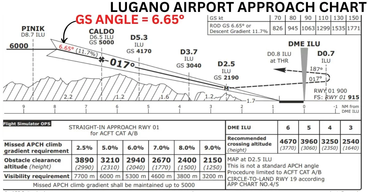
For instance, the normal Glideslope angle is 3 degrees for the ILS approach system. Some airports like London City Airport in the United Kingdom have a GS angle of 5.5 degrees making it one of the steeper ILS approaches.
Lugano Airport in Switzerland features the current steepest ILS Approach with 6.65 degrees of GS angle.
Conclusion on ‘What is an ILS Approach?
With all these important discussions, we have come to the conclusion for the ILS Approach system. We are pretty sure you must have understood all the basics of this precision approach.
In a nutshell, ILS (Instrument Landing System) is a Precision Approach System that provides lateral, and vertical guidance for accurate landing.
CAT I, CAT II, and CAT III are the three categories of the ILS Approach, the higher being the most accurate. CAT III ILS Approach can also execute autoland if the aircraft is properly equipped, and pilots are intensively trained.


